

 Current position > News detail
『EH flowmeter』Related information(clamp on meter|electromagnetic meter|venturi meterrotameter|orifice meter|ultrasonic flow meter|mass flow meter|coriolis mass flow meter|coriolis flow meter|magnetic flow meter|magmeter flow meter|magflow flow meter|mag meter flow meter|electromagnetic flow meter|vortex flow meter|turbine flow meter|thermal mass flow meter|thermal flow meter|rotameter flow meter)
1. What parameters are generally set for an E+H electromagnetic flowmeter?
The conventional setting parameters for an E+H electromagnetic flowmeter mainly include instrument constants, measurement units, pipe diameter, fluid type, calibration parameters, and output signals, which need to be configured specifically according to the on-site working conditions and measurement requirements. 1. Core parameter instrument constant: The unique coefficient calibrated on the nameplate or factory report of each flow cluster simulation and measurement instrument, used to convert sensor signals into actual flow values. Input errors can cause measurement deviation. Inner diameter of pipeline: The actual inner diameter of the pipeline (unit: mm/mm) must be accurately entered, which directly affects the calculation of flow velocity and the accuracy of flow rate. Flow unit: Choose cubic meters per hour (m ³/h), liters per minute (L/min), etc. as needed, consistent with the system display unit
2. Fluid and calibration parameters Fluid conductivity: Set the minimum conductivity threshold of the measured fluid (usually ≥ 5 μ S/cm), below which normal measurement may not be possible. Zero point calibration: carried out when the pipeline is filled with fluid and there is no flow, to eliminate static errors. Full scale calibration: Adjust at a known standard flow rate to ensure full range accuracy (with standard device operation)
3. Signal processing and output damping time: Adjust response speed (unit: seconds), usually set to 1-5 seconds; When the operating conditions fluctuate greatly, increasing damping can stabilize the reading, but it will reduce the response speed. Current output: usually set to 4-20mA correspondi
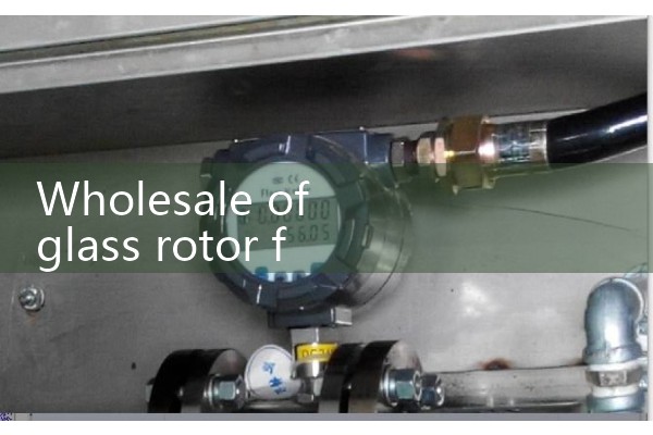
4. Other key settings for flow direction: define forward/reverse flow measurement logic, which needs to be consistent with the actual flow direction of the pipeline. Air traffic control alarm threshold: Set conductivity or signal strength threshold collapse trace to detect pipeline vacancy or incomplete pipeline status. Total Accumulation: It is necessary to reset to zero or set an initial cumulative value, and the unit can be selected from cubic meters/liters, etc. It is recommended to refer to the operation manual of the corresponding model of E+H (such as Promag series major changes) for detailed parameter configuration. Some advanced functions (such as multivariable output and HART protocol settings) require dedicated programmers or software operation.
2. E+H-91WA1- What method is used for measuring ultrasonic flow meters
Ultrasonic flow meters mainly use the time difference method for measurement, which is a common ultrasonic flow measurement technique.. In the time difference method, the time difference of ultrasonic signals propagating in the fluid is used to calculate the flow velocity. Specifically, ultrasonic transmitters and receivers are usually installed on both sides of the pipeline, with signals transmitted from one side to the other while returning in reverse flow. By measuring the difference in propagation time between upstream and downstream, the average velocity of the fluid can be calculated. The advantage of this method is that it does not require direct contact with the fluid, reducing the need for maintenance and cleaning. However, there are also a few cases where Doppler effect is used for ultrasonic