

 Current position > Product detail
『Gas glass rotor flowmeter』Related information(clamp on meter|electromagnetic meter|venturi meterrotameter|orifice meter|ultrasonic flow meter|mass flow meter|coriolis mass flow meter|coriolis flow meter|magnetic flow meter|magmeter flow meter|magflow flow meter|mag meter flow meter|electromagnetic flow meter|vortex flow meter|turbine flow meter|thermal mass flow meter|thermal flow meter|rotameter flow meter)
1. How to determine the calibration pressure of a glass rotor flowmeter? The calibration pressure of a glass rotor flowmeter needs to be determined comprehensively based on the actual working conditions, medium characteristics, and standard specifications. The core parameter is usually 1.1-1.3 times the system working pressure. 1. According to the process system parameters and working pressure range: The calibration pressure should cover the normal pressure fluctuation range of the system. For example, when the pressure of a chemical pipeline is 0.5-1MPa, it is recommended to set the calibration pressure to 0.55-1.3MPa. • Safety margin: A pressure margin of 10% -30% should be reserved to prevent sudden pressure fluctuations from damaging the flowmeter. two According to the industry standard and national standard GB/T 14811-2016, the calibration pressure shall not be less than 1.1 times the maximum working pressure. • Medium type adaptation: The calibration brightness width pressure for gas media is generally 0.1-0.6 MPa, and for liquid media it is 0.3-1.6 MPa (according to HG/T 20570-2013). three The influence of medium characteristics on high viscosity liquids (such as crude oil): It is necessary to increase the calibration pressure by 20% -40% to overcome flow resistance. Corrosive media: The calibration pressure needs to be increased by an additional 15% -25% to ensure long-term stability. four Equipment linkage requirements - If the pressure bearing capacity of downstream equipment (such as pumps and valves) is lower than 1MPa, the upper limit of the calibration pressure should be synchronously lowered. Typical Calibration Pressure Quick Check Table | Medium Type | Working Pressure Range | Recommended Calibration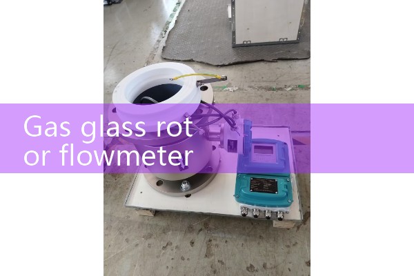
2. Flow calculation formula for glass rotor flowmeter
The flow calculation formula for glass rotor flowmeter is: Q=K × √ (Δ P) or Q=C × A × √ (2g Δ h/ρ), where K and C are instrument coefficients and Δ P is pressure difference.
. 1. Core calculation formula: Glass rotor flowmeter belongs to variable area flowmeter, and its flow calculation formula is derived based on the principle of rotor force balance. The most commonly used basic form is: Q=K × √ (Δ P), where: • Q: volume flow rate of fluid (unit: m ³/h or L/min) • K: instrument coefficient (or flow coefficient), determined by the specific structure, rotor shape and material of the flowmeter, usually provided by the manufacturer after factory calibration, and is the core parameter for flow conversion. Δ P: The pressure difference before and after the rotor (unit: Pa), which is balanced with factors such as the rotors gravity, buoyancy, and fluid viscosity during stable flow, and can be regarded as a constant. Another more detailed and physically meaningful formula is: Q=C × A × √ (2g Δ h/ρ), where • C is the outflow coefficient, which is an empirical coefficient related to the Reynolds number and is usually calibrated by the manufacturer. A: The annular gap area between the rotor and the conical tube (unit: m ²) varies with the height of the rotor. • g: Gravity acceleration (9.8 m/s ²) • Δ h: Pressure head difference corresponding to rotor height change bench roll (unit: m) •ρ: Density of the measured fluid (unit: kg/m ³) 2. Flow reading in practical applications. In practical applications, operators do not