

 Current position > News detail
『Principle of metal float flowmeter』Related information(clamp on meter|electromagnetic meter|venturi meterrotameter|orifice meter|ultrasonic flow meter|mass flow meter|coriolis mass flow meter|coriolis flow meter|magnetic flow meter|magmeter flow meter|magflow flow meter|mag meter flow meter|electromagnetic flow meter|vortex flow meter|turbine flow meter|thermal mass flow meter|thermal flow meter|rotameter flow meter)

1. Principle of Metal Tube Float Flow Meter
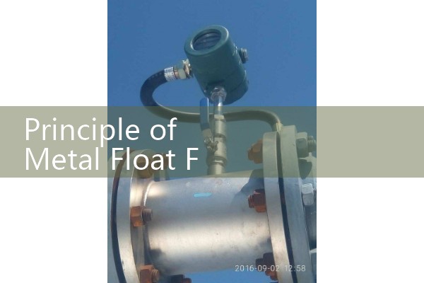
The float of the metal tube float flow meter moves upward with the change of flow rate in the measuring tube, and at a certain position, the buoyancy and gravity of the float reach equilibrium. At this time, the circulation gap area between the float and the orifice plate (or cone tube) remains constant. The annular gap area is directly proportional to the rising height of the float, that is, the position where the float rises in the measuring tube represents the size of the flow rate. The change in the position of the float is transmitted from the internal magnet to the external silver indicator, so that the indicator correctly indicates the current flow rate value. This means that the indicator housing does not come into direct contact with the measuring tube, so even if limit switches or transmitters are installed, the instrument can be used under high temperature and high pressure working conditions.
2. Operating principle of metal tube float flowmeter remote transmission module
The core of the operation of the metal tube float flowmeter remote transmission module is to collect float displacement signals through non-contact magnetic coupling, convert the signals and output standardized electrical signals to achieve remote collection and transmission of flow data, without the need to contact the measured fluid throughout the process.
.1. Principle of magnetic coupling signal acquisition (1) Basic linkage logic 1 The float of the metal tube float flowmeter is embedded with a permanent magnetic steel inside. When the measured fluid flows through the conical metal tube, the float moves up and down along the axis with the change of flow rate.
II. Signal Conversion and Remote Transmission Process (1) Signal Conditioning Calibration 1 The collected weak electrical signals will enter the signal conditioning circuit built into the remote transmission module to complete amplification, filtering, linear compensation, and convert the float displacement into standard flow values. 2. For different application scenarios, the conditioned signals will be converted into universal remote transmission formats, including 4-20mA analog current signals, RS485 digital bus signals, HART protocol signals, etc. (2) Remote data transmission 1 The standardized signal after conversion is uploaded to the remote acquisition controller, DCS system, or SCADA platform through the BiSui matching cable, achieving off-site flow data monitoring and recording.
III. Key Usage Restrictions 1 The remote transmission module should avoid strong magnetic field environments (such as around large motors and transformers), otherwise it will interfere with the induction accuracy of the magnetic sensing components. 2. Explosion proof remote transmission modules should comply with the GB 3836 series explosion-proof s