

 Current position > News detail
『Installation of vortex flowmeter』Related information(clamp on meter|electromagnetic meter|venturi meterrotameter|orifice meter|ultrasonic flow meter|mass flow meter|coriolis mass flow meter|coriolis flow meter|magnetic flow meter|magmeter flow meter|magflow flow meter|mag meter flow meter|electromagnetic flow meter|vortex flow meter|turbine flow meter|thermal mass flow meter|thermal flow meter|rotameter flow meter)
1. Precautions and regulatory requirements for installation of vortex flowmeter
When installing a vortex flowmeter, the following precautions and regulatory requirements must be strictly followed to ensure measurement accuracy, chamber timing, and equipment lifespan:
1. Pipeline laying direction and medium compatibility. Horizontal pipeline installation: The influence of the measured medium temperature on the transmitter needs to be carefully considered.
. High temperature media may cause thermal expansion or performance drift of internal components of the transmitter, thereby affecting measurement accuracy. Suggestion: Avoid direct contact of high-temperature media with the transmitter, and if necessary, use insulation sleeves or extended pressure pipes. When installing horizontally, ensure that the fluid flow direction is consistent with the direction indicated on the flowmeter to prevent abnormal vortex signals. Vertical pipeline installation: Gas measurement: The fluid flow direction can be arbitrary (upward or downward), and due to the low gas density, the influence of gravity can be ignored. Liquid measurement: It is necessary to ensure that the fluid flows from bottom to top to avoid liquid phase separation or interruption of vortex signals due to gravity.Secondly, choose a location away from the vibration source: Vortex flowmeters are sensitive to mechanical vibrations, which may cause detection components (such as piezoelectric crystals) to send signals incorrectly.
. Suggestion: The installation location should be at least 1 meter away from vibration sources such as pumps and compressors, and vibration reduction brackets should be installed if necessary. Avoid installation within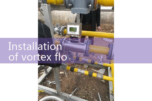
Third, the straight pipe section requires matching of the inner diameters of the front and rear straight pipe sections: The difference between the inner diameters of the front and rear straight pipe sections of the flowmeter and the inner diameter of the flowmeter body should be less than 3%, otherwise measurement errors may occur due to uneven flow velocity distribution.
. Suggestion: Before installation, check the pipeline design drawings to ensure that the inner diameter is consistent. If there is a change in pipe diameter, a transition should be made through a tapered/expanding pipe to avoid sudden changes. Length of straight pipe section: Upstream straight pipe section length: generally required to be ≥ 15 times the pipe diameter (DN), and for complex working conditions (such as including valves and elbows), it needs to be extended to 20 times the pipe diameter. Downstream straight pipe section length: ≥ 5 times the pipe diameter, ensuring that the fluid is stable before entering the flowmeter. 4. Valve and Bypass Configuration Protective Valve Installation: In situations where detection components may be damaged (such as high pressure, high temperature, corrosive media), front and rear globe valves and bypass valves need to be installed. Globe valves are used to isolate flow meters for easy maintenance or rep